Rosetta Design 
Rosetta Design is a sophisticated model editor that allows the user to edit model files in their own working environement (called a Workspace). This Rosetta Component features different Views, which the user can switch between, and different tools that make the navigation and the use of the editor user friendly.
We recommend that users get familiar with Workspace management basics prior to reading this Rosetta Design section.
In this section, you will learn about:
- Rosetta Design Window
- Rosetta Design Model Explorer
- Rosetta Design Content Assist
Rosetta Design Window 
Rosetta Design Window is the main space displayed by default in a Workspace Window. When the user uses other Rosetta Components or Features such as Rosetta Ingest, Projection, Validation or Reports, the Rosetta Design Window occupies the top half of the Window (unless the user expands that other Component or Feature to be full-screen).
The Rosetta Design window comprises 3 parts:
- The Rosetta Design View bar
- The model content (shown in accordance with the selected view)
- The Rosetta Design Toolbar
Rosetta Design View bar 
To visualise a model, the user can choose from different available views in the Rosetta Design View bar at the top-left of the Rosetta Design Window.

Different Views: different representations of the same component 
Rosetta Design comprises the following views:
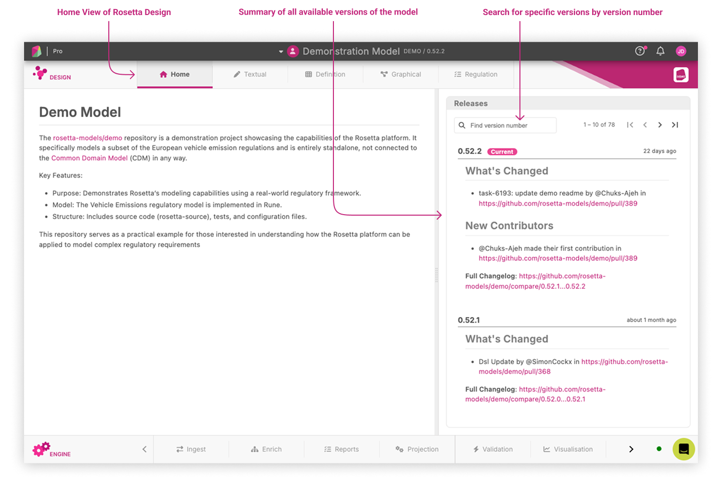
- Home View
The Home View serves as the central hub of Rosetta Design, offering a comprehensive overview of the model’s structure and purpose. It is particularly valuable for gaining a clear understanding of the model’s overall scope and intent.
This view also provides convenient access to all available versions of the model through a resizable right-hand panel. Users can easily see a summary of the changes made in each version directly within the panel and search for specific versions by their version numbers.
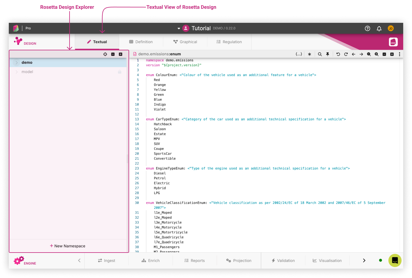
- Textual View
This view of Rosetta Design displays functional expressions of data and business logic of a model as text. This is where users primarily develop the logical model using the Rune DSL syntax. The Rosetta Design Model Explorer is displayed by default on the left hand-side and you can resize it by dragging the right hand-side of the panel.
The Rosetta Design Model Explorer displays the logical model as a tree. The tree is displayed in a hierarchical structure and the user can expand and collapse nodes to display the contents of the tree.
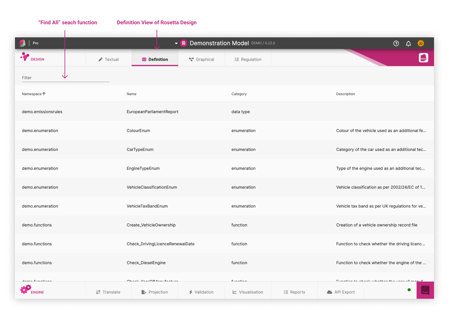
- Definition View
This is a view displaying all the components of a model in a table. A description of each component is available based on information edited from the Textual View. This view is useful to screen concepts and definitions that populate a model thanks to the Find All search function. It is particularly appropriate for subject-matter experts from the domain being modelled, who want to quickly access a glossary of model components.
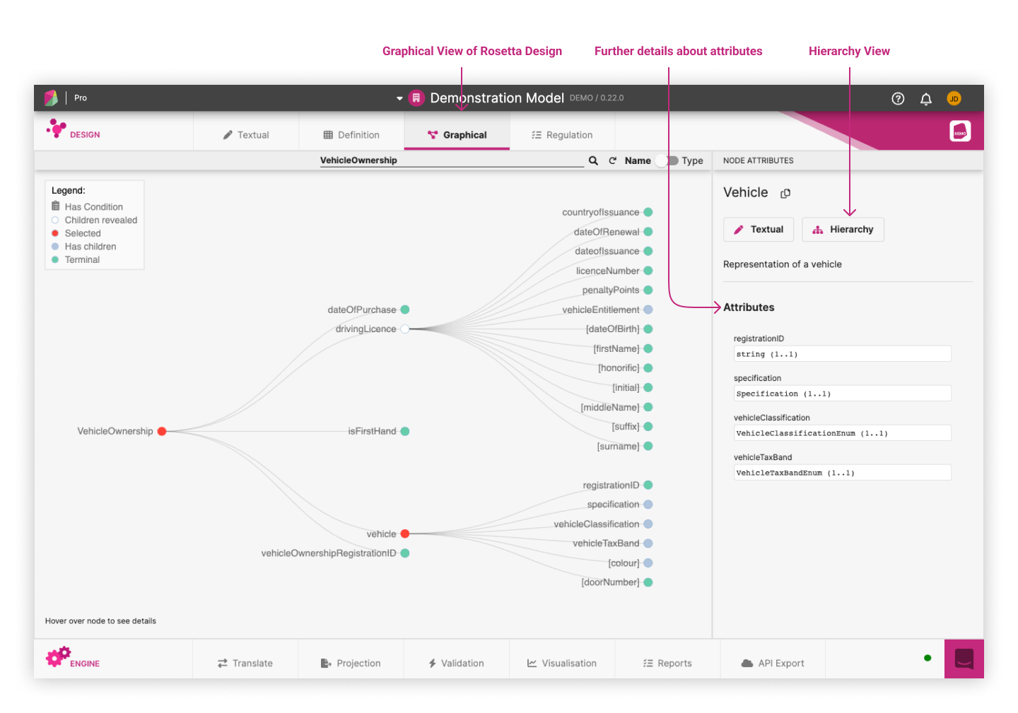
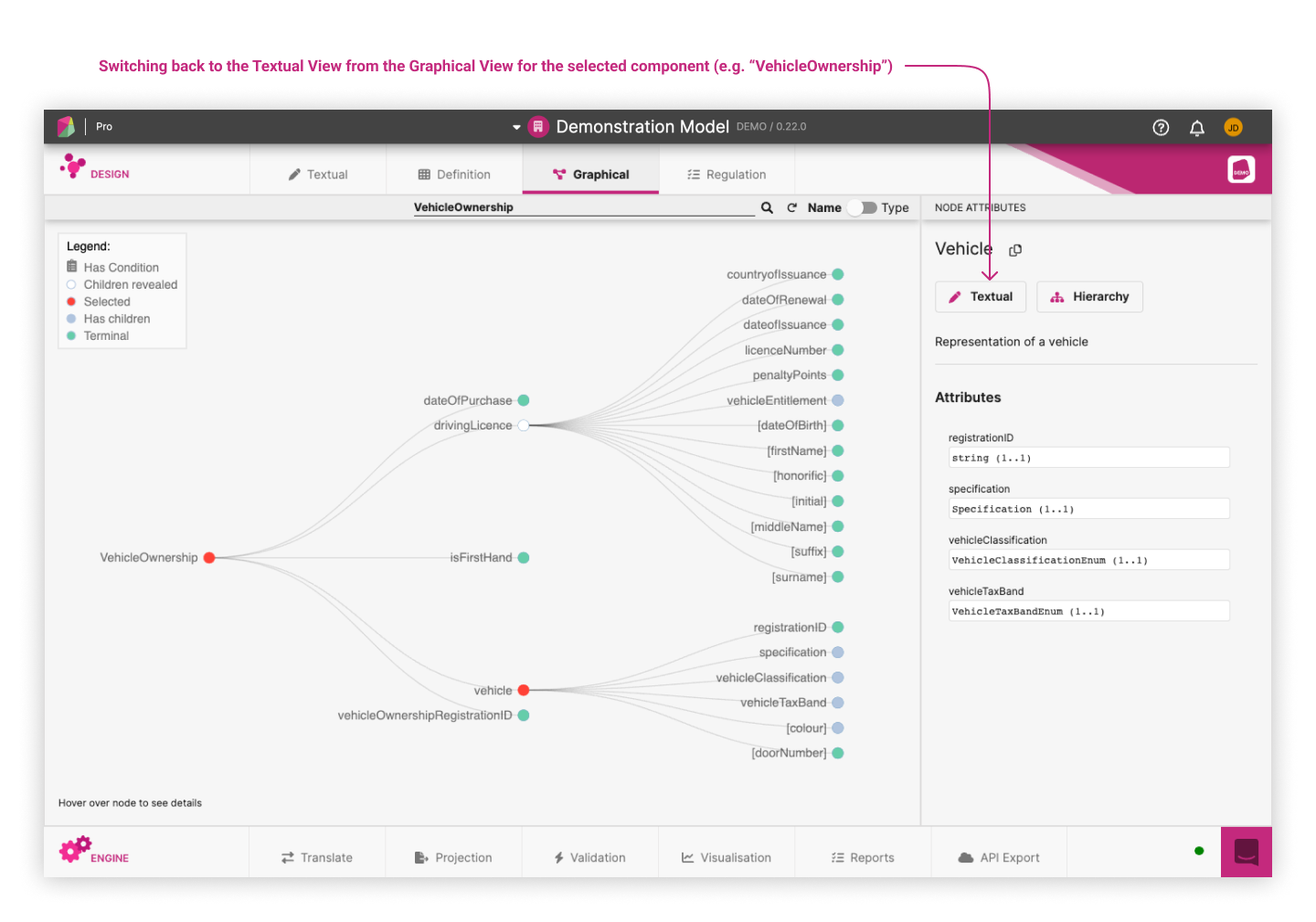
- Graphical View
This is a view displaying any selected part of a model as an interactive graphical tree. It indicates the relationship (either through inheritance of inclusion as attribute) between the different model components. This view is particularly useful to test and validate progress on model editing in the Textual View, thus accelerating logical modelling. It also helps easily locate a specific data field in the data model and the corresponding path from a root type, which facilitates mapping exercises and the writing of rules.
The following example based on the Demonstration Model displays a graphical representation of the VehicleOwnership with its attributes and inheritances (i.e. when a component extends another component and inherits from its attributes).
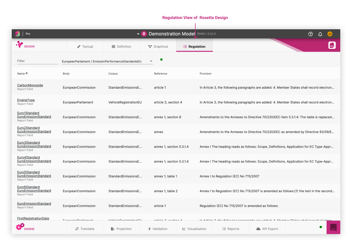
New Regulation Panel (Documentation Reference View) 
When the new regulation Panel is available a toggle will be displayed at the top right of the panel, this toggle will switch between the legacy and new view.
The new regulation panel focuses on document references (docRefs) within the model, offering users a comprehensive overview which comprises of three vertical panels, each grouping and organising the docRefs."
Body Corpus List
The initial column groups docRefs based on Body Corpus, allowing users the ability to pinpoint their area of interest.Hierarchical Rule Types and Segments
The middle column displays all docRefs associated with the selected Body Corpus in an hierarchical list. These are grouped by rule type and subsequently by docRef segments, presenting a structured overview.Provision Details
Column three is a flat list with details about each document reference. The details displayed depends on the model but the available items are:
- Provision
- Rationales
- Reporting Rule
- Provisions on the same rule
- Dependent provisions
Switching from one View to another 
The user can easily switch from one view to another, which facilitates the navigation through the different representations of a same model component:
- From the Graphical View to the Textual View: by clicking on the
Textual Viewbutton in the right hand-side panel.
- From the Regulation View to the Textual View: by clicking on the name of the reporting field displayed as hyperlink, or on the rule definitions of the information summary for the considered reporting field.
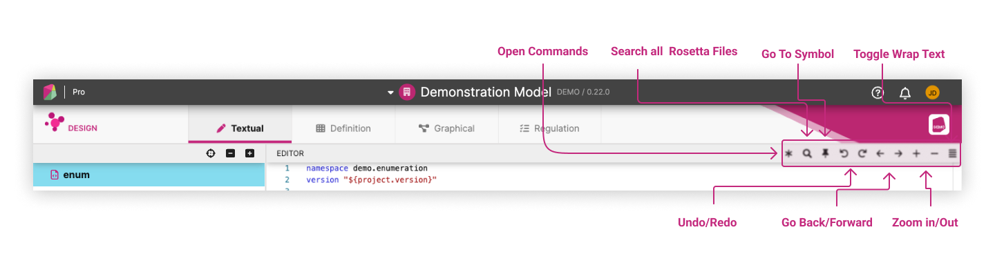
Rosetta Design Toolbar 
All the editing tools available are accessible in the Rosetta Design Toolbar shown at the top-right of the Textual View.
Rosetta Design Toolbar comprises of
- Open Commands: List of editor tools
- Search All Rosetta Files: Search engine for free text across all model files
- Go To Symbol: Search engine for model elements and types across all mode files
- Undo/Redo: Undo/Redo functionalities
- Go Back/Forward: Back/Forward page navigation within the Textual View
- Zoom In/Out: Zoom in/out of functional expression display in the Textual View
- Toggle Wrap Text: Formatting of the lines in the Textual View (expanding or collapsing, with no model impact)
<- and -> commands provided in the Rosetta Design Toolbar to navigate within the Application, and not their browser's <- and -> commands (with effect being to close their Workspace instead).Most of these tools and commands are meant to be familiar to users of traditional dev kits, albeit much slimmed-down in order to resemble a basic text editor which non-developers can also get comfortable using.
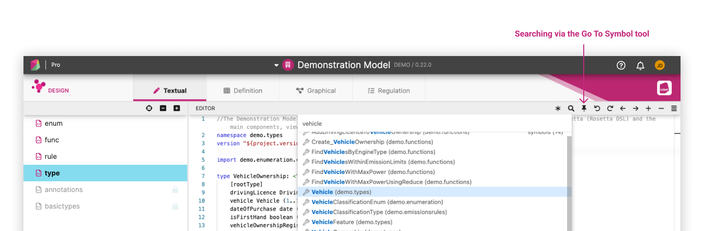
An important difference with a traditional text editor is that model elements are hyper-linked in the Application. This implies that each model element can be navigated to and from:
- either by searching for the element directly, via the
Go to Symbolcommand in the Rosetta Design toolbar, here used to search for thevehicleelement in the Demonstration Model
- or by pressing
Ctrl/Cmd+ Click on the element name wherever it appears in the Rosetta Design Window. Simply hovering over the element brings its description to the foreground (illustrated here with theSpecificationType in the Demonstration Model):
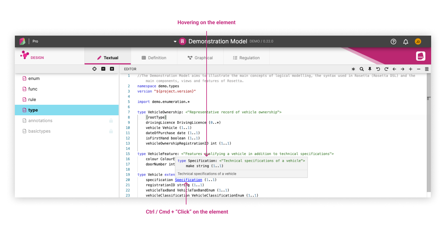
This is akin to having a text editor associated to a dictionary, where any occurrence of a word from that dictionary provides a handle to navigate to the definition of that word.
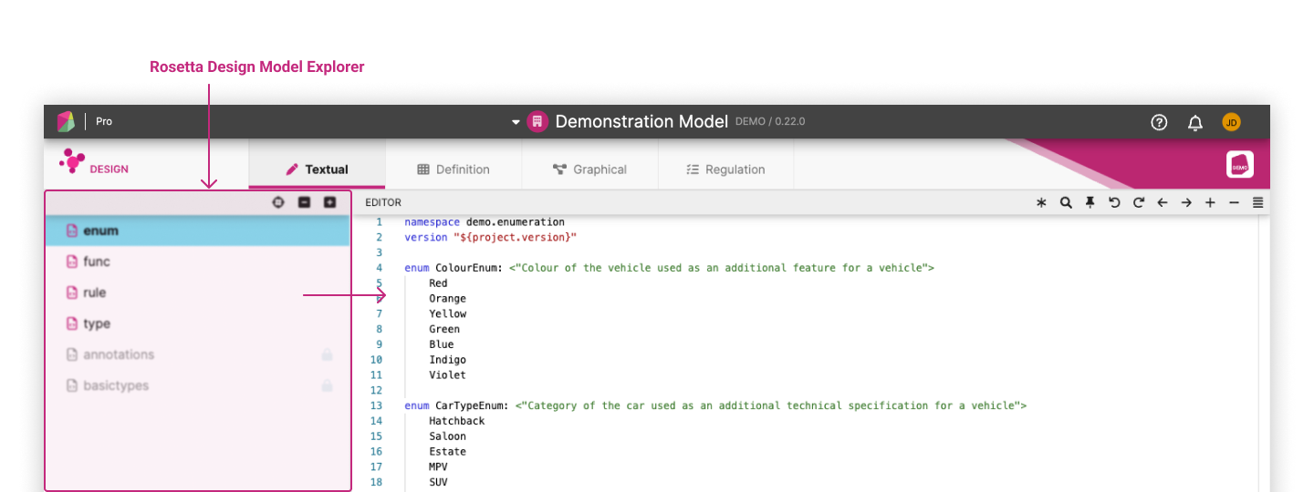
Rosetta Design Model Explorer 
Rosetta Design contains a list of model files that have been copied across from the chosen model source-control repository and into the user Workspace. Each file is accessible by clicking its name in the left-side Model Explorer panel of Rosetta Design. The current file opened in the right-hand side Rosetta Design Window is highlighted in the Model Explorer:
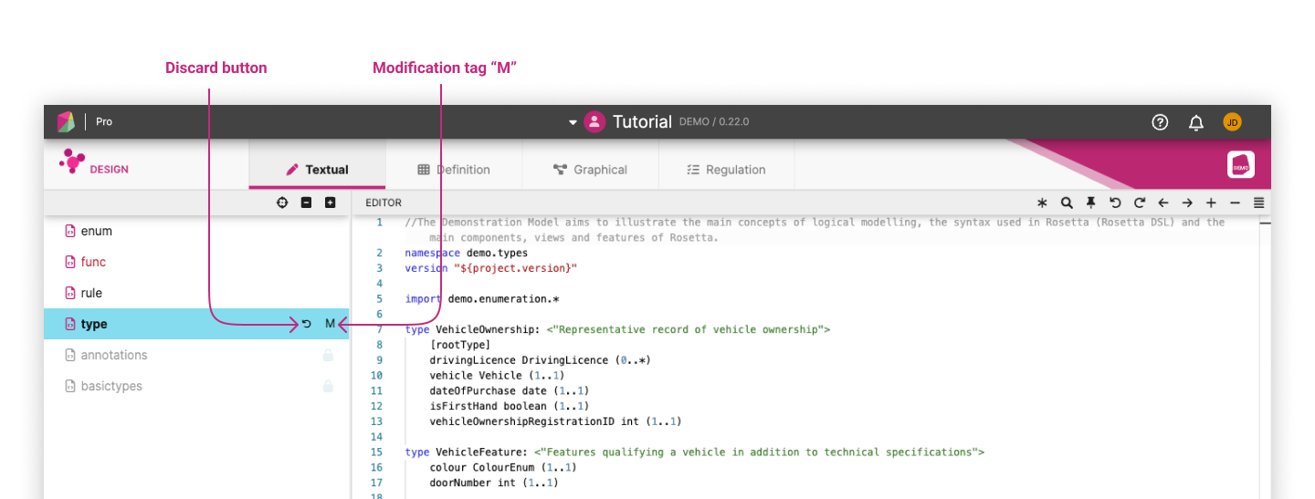
The Rosetta Design Model Explorer tracks model changes in the Workspace by annotating modified files with the initial M. Any changes can be discarded and reverted back to the original source-control
version by clicking on the Discard back arrow:
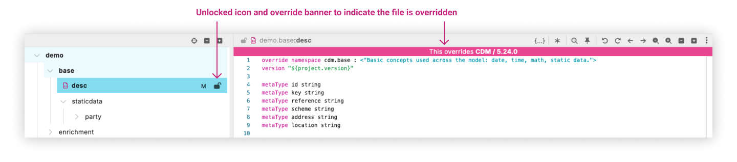
Overriding Parent Model Files 
For some models, Rosetta allows namespaces from parent models to be overridden for workspace-specific customization.
If the parent model file can be overridden, there will be an unlock icon in the top right-hand corner of the file — clicking it will override the
namespace and enable editing.
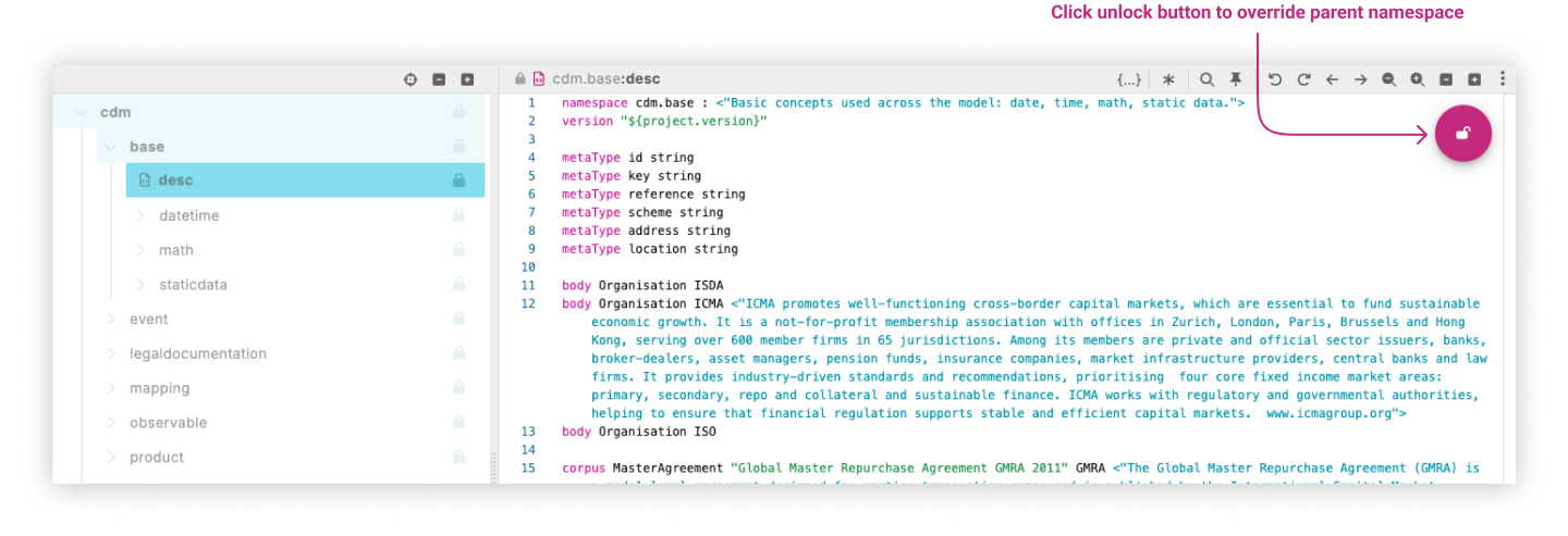
Overridden files are marked with an unlock icon in the file explorer. The M icon would also appear for both direct changes and parent model overrides.
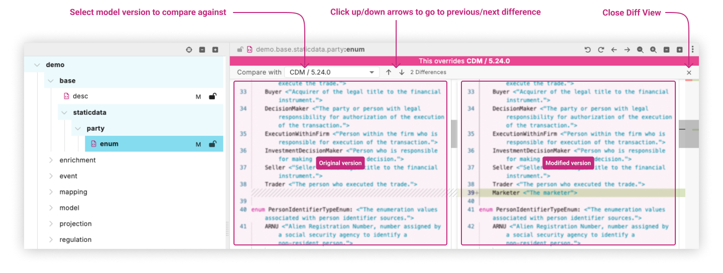
Viewing Differences Between Model Files 
After overriding a file or making changes to an existing file, you can view the differences between your changes against other versions:
Accessing the Diff View: Click on the
Micon in the file explorer next to a modified or overridden file to open the diff editor view.Navigating Differences: In the diff editor view, you can:
- See the number of differences between files
- Navigate between differences by clicking on the up and down arrow icons
- Toggle between comparing against the parent model or the workspace’s base model using the dropdown menu
- Understanding the Comparison Options:
- You can only compare against the parent model if the file was overridden
- For modified files that aren’t overridden, you can compare against the workspace’s base model
- Reading the Diff View:
- By default the left hand-side section displays the workspace’s base model for comparison but this can be changed with the parent model version toggle mentioned above.
- The right side shows your current version with changes
- Differences are highlighted for easy identification
- Closing the Diff View: There are two ways to close the diff editor view:
- Click the ‘X’ icon in the top-right header of the editor
- Toggle the
Micon on the selected file in the file explorer
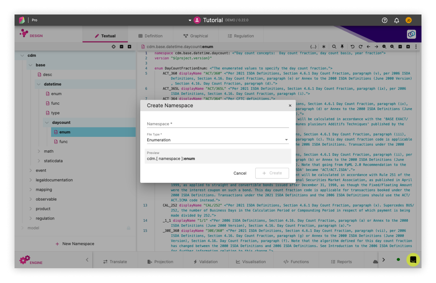
Add New Namespace 
To add a new namespace to the model, follow these steps:
- Open the Rosetta Design Model Explorer panel in your application
- Locate the “New Namespace” button at the bottom of the panel and click on it
- A “Create Namespace” popup will appear, divided into three sections: Namespace Path, File Type, and Namespace Preview
- In the Namespace Path section, enter the desired path where you want the new namespace to be stored. This path determines the location for the namespace and its associated file
- Choose the appropriate File Type for your namespace in the respective section
- The “Namespace Preview” section will display a preview of the new namespace structure based on the provided path and file type
- Take a moment to review the namespace preview to ensure it aligns with your expectations and requirements
- When you are satisfied with the namespace details, click the “Create” button
- The new namespace will be added to the model, and the associated file will be automatically selected for further editing or customization
By following these steps, you can easily add new namespaces to your model.
Rosetta Design Content Assist 
Rosetta Design features a number of content-assist tools to guide users through editing the model:
- Syntax highlighting
- Syntax checking
- Auto completion
- Auto compilation
We recommend that users get familiar with the Rune DSL documentation for how the model is expressed, prior to reading this section.
Syntax Highlighting 
Rosetta Design highlights different syntax features to improve readability of the model being edited, as shown in the colour-coding schemes displayed in the below example and further down in the documentation:
The model elements being highlighted in different colours are:
- DSL syntax keywords like
func,aliasetc. - text (as string elements between
"") - numbers
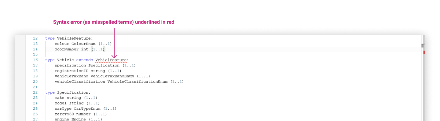
Syntax Checking ("Validation") 
The syntax checking feature works similarly to spell checking in a text editor, with the model providing the underlying dictionary. However, syntax checking is strictly enforced against the formal Rune DSL: the model is invalid if there is any syntax error.
In the below example, we introduce a syntax error by mis-spelling the term VehicleFeature in the Demonstration Model. The resulting term gets underlined in red as VehiclFeature is not a valid term in the dictionary:
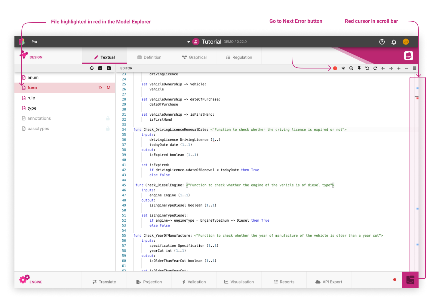
Often, editing the model in one place may trigger syntax errors in some other place. To aid users identify those, files containing errors are shown in red in the Model Explorer and a red cursor in the right-side scroll-bar points to the line(s) where errors appear. Users could also review the errors one by one by clicking on the Go To Next Error button next to the Rosetta Design Toolbar.
Auto Completion ("Scoping") 
To prevent syntax errors occuring in the first place, Rosetta Design can guide editing of the model by offering auto-completion suggestions in a drop-down list as the user types. Auto-completion is aware of the surrounding scope in which the model is being edited and offers suggestions that are relevant to that scope.
In the below example, the user is editing a type (CarOwnership) in the Demonstration Model and is looking to complete the type of one of its attributes (of name: vehicle). As they start to type a V, Rosetta Design is aware that the user is able to use Vehicle as a type, because it already exists as a defined type in the model:
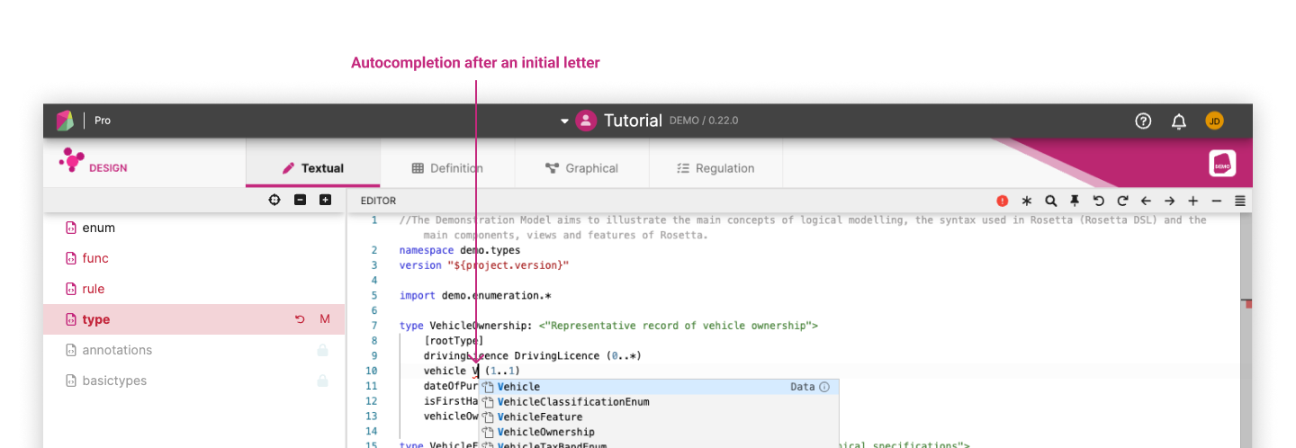
The auto-completion tool-tip can also be invoked manually by pressing Ctrl / Cmd + Space.
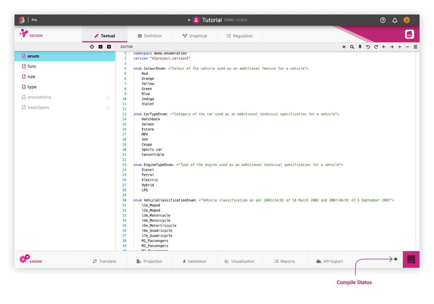
Auto Compilation 
As soon as a model is syntactically correct in the Rune DSL, it becomes executable and Rosetta Design will automatically try to generate and compile executable code from it. A traffic light icon at the bottom-right representing the status of the model compilation (by default: from Rune DSL into Java) is updated in real-time as the user edits their model.
The traffic light colour code corresponds to the following status:
green: the model compiles without any issueamberand spinning: compilation is runningamberand static: the model cannot compile due to syntax errorsred: the model compilation fails
Because the model syntax is pre-validated, the code generation process should normally generate valid code that compiles. However, in certain cases this process could fail with the compilation ending-up in red status with an error message being reported. There are 2 cases where this could occur:
- The Rune DSL syntax validation is not strict enough to capture all cases where invalid code could be generated.
- The compilation depends on some "static" code (i.e. code that is not dynamically generated from the model), and the model has introduced incompatibility with such code.
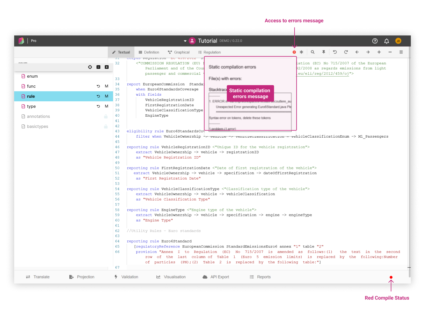
Users are advised to contact the Rosetta support team who can help resolve when they encounter such issue. Users can use the in-app chat to raise a request and copy/paste the error message reported in the application.
The Rosetta Design application is constantly being improved and looking to eventually eliminate the occurrence of the above 2 issues. This requires removing all static code by having all code driven from the Rune DSL syntax, and making the Rune DSL syntax validation comprehensive. Every issue occurrence raised will help the support team identify the gaps that may still exist and which should be addressed.
See Rosetta Code Generation for further technical information on how the code generation process works.